
Interpreting TactileGlove Data for Practical Use Cases
How to get the best out of TactileGlove
Executive Summary
This white paper provides guidance on understanding data collected by the PPS TactileGlove sensor, particularly in basic gripping and lifting tasks. It covers what to expect, how well the sensor performs, ways to reduce errors, and how to accurately interpret force and pressure readings.
The PPS TactileGlove is an advanced tool for testing ergonomics, offering precise measurements of hand pressure during various activities. Its high-speed data capture, consistency, and comfortable design make it invaluable for assessing comfort, fit, and safety in product development.
Using quantified data from tactile interactions is becoming standard practice in ergonomic testing. This shift allows designers to move from relying solely on subjective feelings to having concrete measurements, facilitating better design decisions and reducing the need for multiple design revisions.
However, understanding and interpreting this tactile data can be challenging. This document focuses on reliably measuring and interpreting hand pressure data in a straightforward scenario, such as lifting a dumbbell. It covers expectations, interpretations, and recommended methods to consistently obtain accurate ergonomic measurements.
By providing clear guidelines for utilizing TactileGlove data, this document aims to increase confidence in its measurements, enabling reliable assessments in real-world applications. This, in turn, supports informed design choices that will shape the future of ergonomic product development.
What is TactileGlove, and why is it used?
The TactileGlove in a Nutshell
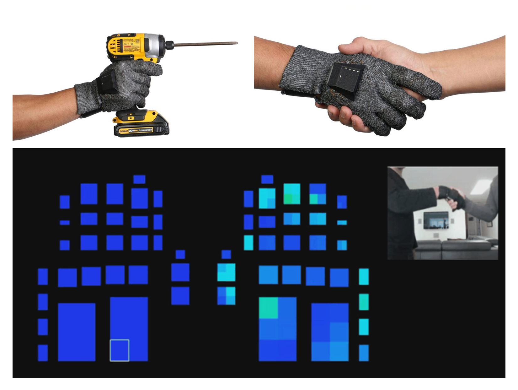
The PPS TactileGloves are equipped with pressure sensors distributed throughout the palm and fingers. These sensors enable accurate measurement of the pressure applied by the hand during various activities. With 65 highly sensitive sensing elements in each glove, it can effectively measure almost any hand operation.
One notable feature of TactileGloves is their wireless and battery-powered design, which allows users to move freely without constraints. Unlike other glove sensors, TactileGlove permits full range of motion, providing a natural testing environment.
The high-resolution pressure sensing and mapping capabilities of TactileGlove facilitate research on hand movements during different tasks. Additionally, it aids in analyzing comfort and ergonomics by providing visual feedback on hand interactions.
TactileGlove finds extensive use in the design and development of tools and equipment intended for long-term use, aiming to maximize operator comfort and reduce stress and fatigue. It is also utilized in research to quantify tactile sensations and to teach intricate hand techniques in various fields such as medicine, sports, and the arts.
In summary, TactileGlove is valuable for any hand-based application or design task where subjective operator sensation or quantified data is necessary for performance monitoring or compliance. It helps designers and users understand tactile interactions by transitioning from abstract qualitative observations to precise quantitative measurements, leading to improved outcomes.
Theory of Operation
The TactileGlove operates using a concept common to many other products made by PPS. It utilizes flexible electrodes arranged as parallel plate capacitors. These capacitors detect changes in capacitance when pressure is applied. By calibrating the device, TactileGlove converts the measured capacitance into pressure readings.
To understand this process, imagine a simple formula P = F/A, (F = PA in this case) where P is the pressure, F is the force, and A is the surface area over which the force is spread.

In simpler terms, pressure is the amount of force applied per unit area. TactileGlove calculates this pressure by measuring the change in capacitance and relating it to the applied force.
Now, when we talk about the glove's operation, it integrates the pressure across its surface area to determine the total force acting on it. This total force can be visualized as a vector, pointing perpendicular to the surface. TactileGlove assumes that pressure is evenly distributed across its sensor elements, treating them as flat and parallel surfaces when estimating the total force.
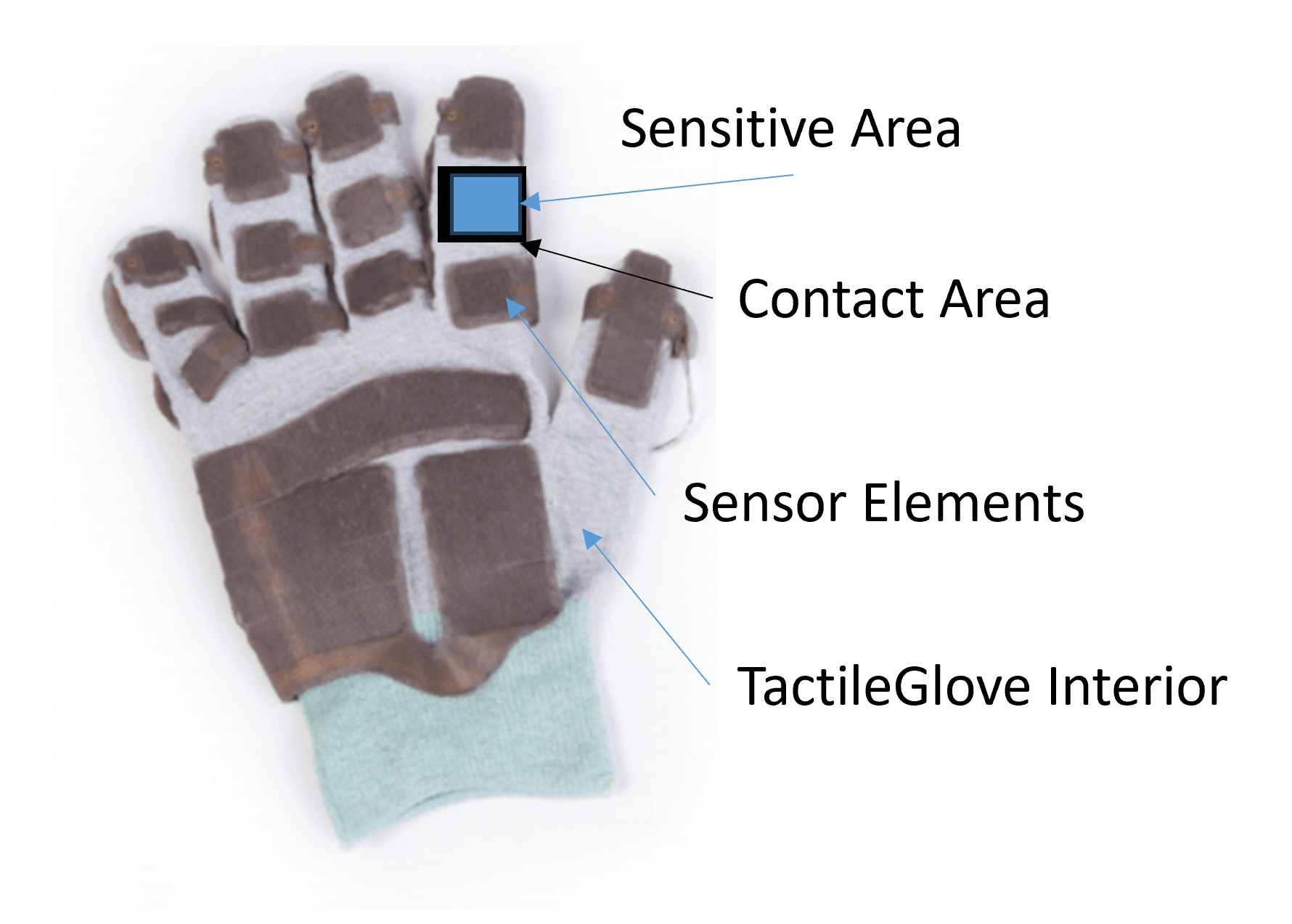
It's important to note that TactileGlove distinguishes between two areas: the contact area and the sensitive area. The contact area includes the parts of the glove where the hand makes contact with objects. The sensitive area, on the other hand, is where the sensor elements are located and pressure readings are taken. Only pressure applied to or loads transferred through this sensitive area are reported by TactileGlove.
Understanding this distinction is crucial when interpreting tactile results. The sensitive area may not necessarily match the contact area with the object being touched. Therefore, TactileGlove provides insights into the pressure and force exerted on specific areas of the hand, helping researchers and designers better understand tactile interactions.
Calibration and Verification
Calibration Method
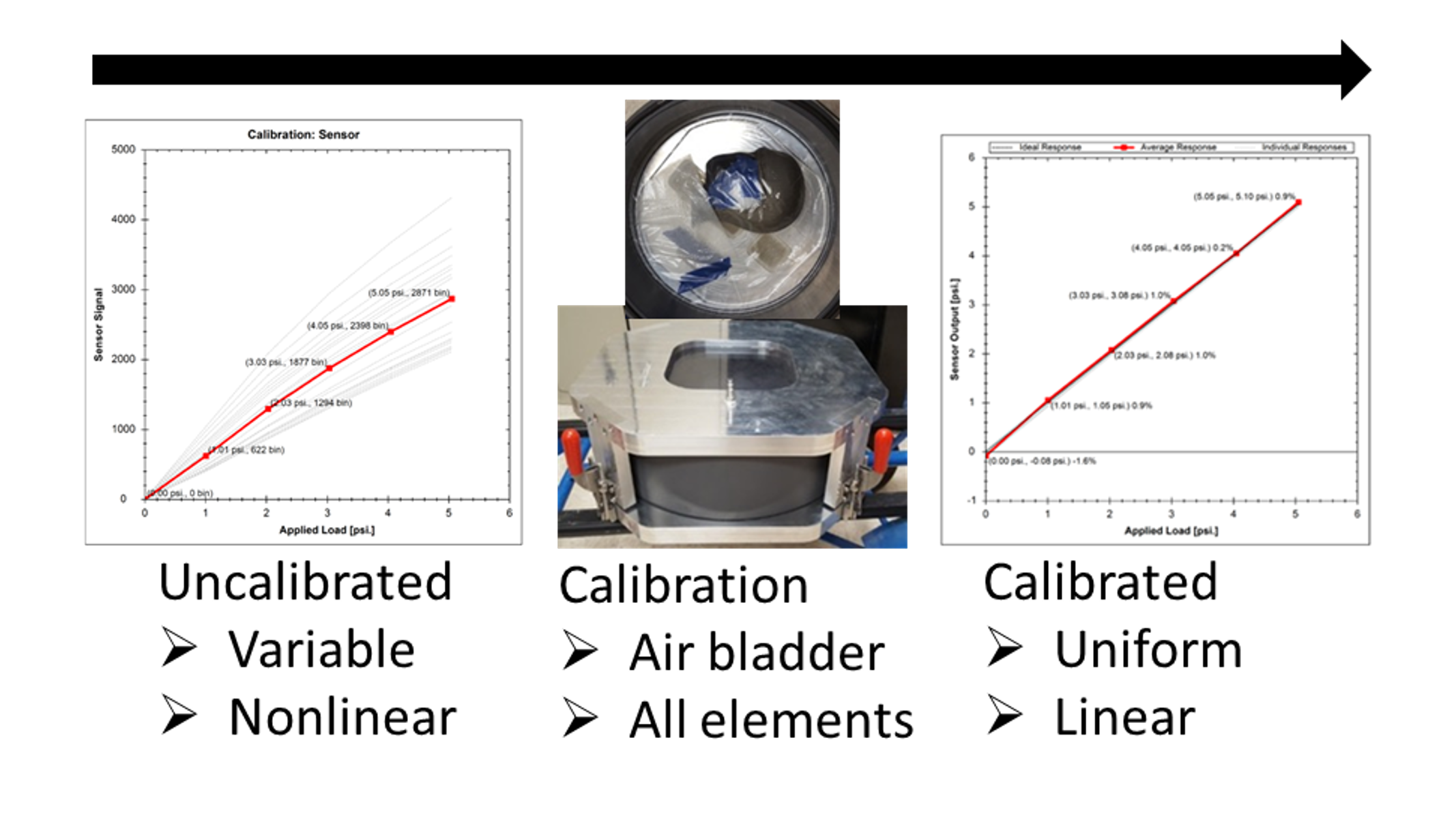
The TactileGlove undergoes a rigorous calibration process in a controlled test environment using an air bladder, ensuring consistent and accurate readings within their specified ranges. During calibration, the gloves are placed flat against a rigid plate, allowing the bladder to evenly compress the sensing elements. Pressure is gradually increased in steps, and detailed calibration responses are generated using mathematical functions.
This calibration process is conducted under controlled temperature and humidity conditions to maintain accuracy. A bladder with minimal stretching capability is used to ensure confidence and repeatability in the performance of the sensors and the calibration chamber. As a result of this meticulous calibration, TactileGlove achieves an impressive linearity error of less than 2%, with repeatability within 3% of the sensor's rating. Additionally, it boasts a signal-to-noise ratio (SNR) of at least 500:1, further enhancing its reliability and accuracy.
Trusting the Calibration
The calibration process of the TactileGlove is designed to maintain accuracy throughout its lifespan. To verify its calibration, you can use a simple weighing scale or a load cell if available. It's recommended to use a matching pad to ensure that the load is applied uniformly to a specific area of interest. This method can provide assurance in the accuracy of the calibration if conducted meticulously.
For instance, when testing a single element cluster by placing it on a load cell or scale with a matching pad, the readings obtained from the glove should closely match those from the reference device, within the specified accuracy range. However, it's important to note that this method is not suitable for checking the entire glove due to potential errors, as explained further in the section on error sources.
When examining individual elements, it's crucial to tare (Zero) the glove in the test position, meaning the hand is positioned as it would be during normal use. This ensures that any residual values are properly accounted for.

If the sensor appears undamaged but still provides unexpected values during such tests, it could be due to one of the three main error sources discussed in the following section. Alternatively, it might require specific interpretation based on the application, as detailed in the applied example.
General Error Sources and Mitigation
Using the wrong size glove
One common issue affecting the accuracy of TactileGlove readings is using the incorrect glove size. If the glove is too large, it may move excessively or stretch, while a glove that's too small can be difficult to handle and could lead to damage. Furthermore, an ill-fitting glove may not provide a natural tactile experience.
Moreover, the accuracy of the output can be significantly impacted by using the wrong size TactileGlove. For example, if the pressure-sensitive elements are optimally positioned for a medium-sized glove, using gloves of other sizes can result in suboptimal positioning of the sensor elements. This can lead to inaccurate readings.
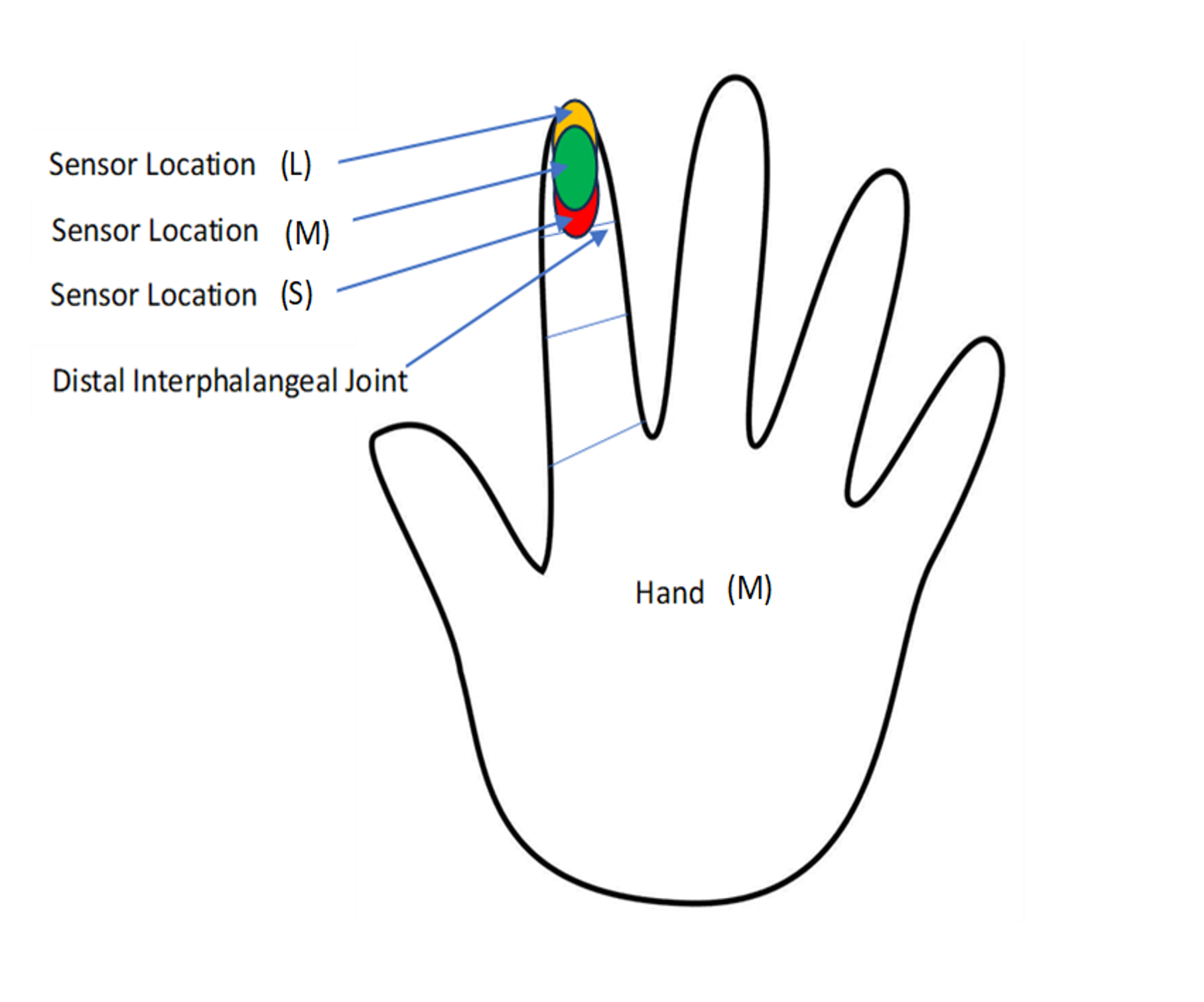
The image shows how this can happen.
Let’s take glove size (M) as an example. The pressure-sensitive elements are positioned optimally on the hand, such as at the centre of the distal phalanx. However, using gloves of different sizes on the same hand would place their respective sensor elements in less-than-ideal positions. In the worst-case scenario, if the glove is too small, the sensors may shift towards the distal interphalangeal joint. This could lead to unwanted bending of the sensors and inaccurate readings. Conversely, if the glove is too large, the sensor elements may be pushed towards the fingertip, reducing the contact area between the finger and the sensors, resulting in inaccurate readings as well.
This issue affects all sensor elements, not just those illustrated. To minimize errors, it's crucial to select the appropriate glove size based on the sizing chart provided. This ensures the optimal positioning of sensor elements and enhances the accuracy of the TactileGlove system.
Temperature/Environmental Effects
The TactileGlove calibration remains reliable under various environmental conditions. However, activities like holding a hot cup of tea or working outside in cold weather can affect measurement accuracy due to temperature changes. This impact is known as the temperature coefficient.
To minimize these effects, it's recommended to use the device within its recommended operating temperature range. Before taking measurements, allow for a 10-minute acclimatization period while wearing the glove. Alternatively, you can use environmental control measures or insulation between the glove and the object being measured. Although algorithmic adjustments in post-processing are possible, they can be complex. Therefore, insulation is the preferred method, especially in extreme temperature conditions ranging from 0 to 50 degrees Celsius.
Improper Tare Position
Setting the TactileGlove to zero, also known as "taring," is crucial for managing any creeping or residual effects. Residuals can occur due to the movement of other sensor elements when loading or adjusting them into position.
By zeroing the sensors in a position that accurately represents the intended usage, errors can be greatly minimized. The accompanying chart illustrates this effect in an example of a cylinder grip, where no external load is applied.

Contact Mechanics

In addition to glove sizing, ensuring proper engagement between the sensor elements and the object of interest, as well as between the fingers/hand and the sensor elements, is crucial. When the sensor elements fully engage with a tactile feature that is at least the size of the element, the glove provides accurate reporting. However, accuracy decreases nonlinearly when the contact area is smaller than the sensor element.

Consider a scenario where a single element is loaded by different geometric shapes. Each case has a different contact area with the element, leading to varied responses under load due to sensor electrode deformation. At low loads, all cases behave normally, but at high loads, electrode deformation affects performance.
This decrease in accuracy can be caused by tactile features in the application or, in the case of shape 'C', by improper glove sizing altering the contact area between the hand and the element. Rarely, bunching of the glove material can also cause this issue.
To address this, load spreading materials can be used on the glove or between the glove and the object. Ensuring the glove material lies flat over the elements or applying post-processing corrections based on empirical measurements of accuracy reduction versus feature size are other solutions. However, these corrections are device-specific, as the relationship between hand, glove size, and tactile object varies depending on the specific use case.

The above example addressed the importance of ensuring that the applied load is evenly distributed across the sensing element. Now, let's consider a situation where ensuring the applied load passes through the element at all. Sometimes, force is applied to an area where there is no tactile element, which is referred to as a force short. As a result, the total load on the object may not be accurately reported by the TactileGlove, even though the glove accurately measures the force or pressure at the element locations.
This discrepancy doesn't necessarily require immediate mitigation because the gloves are correctly measuring the forces at that specific point of the hand, which may not always align with the total force applied to the object. However, if precise values of the total force are needed, measures must be taken to reduce load shorts. This can be achieved by using spacer pads on the tactile elements so that only the tactile elements come into contact with the object. Alternatively, post-processing techniques can integrate the measured element pressures over the remaining hand contact area, which is determined empirically.
Although subtle, this issue is important and will be further explored in detail in the following worked application example.
Applied Application Interpretation
Worked Application: Lifting a Dumbbell
Let's examine a practical example of using the TactileGlove: lifting a dumbbell. This example is relevant for analyzing tool and sports equipment design, as well as sports science, but it's also applicable in various other contexts.
In this scenario, we encounter several potential sources of measurement error mentioned earlier: the loads fall within the TactileGlove's rating, the dumbbell has a smooth geometry comparable to the size of the sensor elements, there are different conditions of use that reveal potential challenges, and the forces involved are straightforward to understand and visualize, allowing for clear conclusions.
The illustration below depicts three cases where a 4.5 kg plastic/concrete dumbbell is lifted and held steady without any movement. Each case is accompanied by specific observations:
Weight resting on the fingers only
Finger elements are well engaged with the object, and so total load from TactileGlove does yield the object mass correctly!
It can be observed that most load is taken by the index and middle fingers, but considerable load is on the ring finger too.
Hand wrapped gently around (some palm area)
The finger elements are well engaged, but the object has rolled back onto the palm, touching an area without tactile elements, resulting in total object mass reported being smaller than the true mass. Loads on the fingers/elements are still correct, and are showing a load redistribution, with most load now on the index finger, with the rest transferred to the palm. The reduced load on the ring finger suggests this is more comfortable (it certainly was!)
Hand firmly gripping the dumbbell
Here the elements are well engaged, with some areas without tactile elements, but now the load reported does not correspond with the true object mass due to the grip force.
All elements show increased load, but it is well distributed and so still comfortable. In this case it is element pressures that indicate comfort and fit, rather than total load. Object mass can be backed out of this measurement, but it requires a free body diagram (FBD)

Interpreting Lifting Forces
In condition 1, where the load is directly transferred through the elements without any load shorts, the interpretation is straightforward. The loads sum up to the correct value, allowing for the determination of both the finger pressures and the object mass.
However, in condition 2, where the load is transferred through the elements and some insensitive areas (resulting in load shorts), the interpretation becomes more complex.
In this case, the finger loads (and palm too) are accurately reported because they were tared and verified beforehand. Therefore, conclusions about localized pressures or forces can be safely drawn. We observe a decrease in finger loads as some of the load is transferred to the palm, along with a redistribution of the finger loads, indicating a shift in the mass distribution and potentially affecting comfort.
Since lateral forces are minimal and the reference load of 4.5 kg is known, the difference in load can be used to roughly estimate the insensitive area or total contact area. This estimation can be useful in later experiments to determine the object mass if needed.
Interpreting Grasping Forces
Condition 3 presents the most complex example, which mirrors many real-world scenarios involving both a static load (the object mass) and grip or grasp forces.

When examining individual element loads or pressures, they are reported accurately and can be readily compared and interpreted in different situations. In this case, there's a general increase in load across all digits, indicating a similar object holding pattern as in condition 2 but with stronger grip. Additionally, the inclusion of the thumb wrapping around the top of the bar is evident. This information is valuable for establishing a comfort baseline for this particular dumbbell, comparing comfort levels with other dumbbells, or visualizing variations in grip distribution over time or among individuals. Such analyses showcase TactileGlove's capability in quantifying sensations and detecting subtle changes over time or between experiments.
Further insight into this application beyond TactileGlove's current reporting capabilities can be gained by considering the positions of the tactile elements on the dumbbell. With this additional context, the total object mass and directional loads can be determined using a subsequent free body diagram (FBD). TactileGlove primarily measures pressure and integrates it over the element area to derive forces, thus lacking the ability to handle the vector nature of forces without user-provided context. With this context, precise measurements of both localized forces or pressures (crucial for comfort and fit) and total vectorized forces (important for assessing effort, work, and unknown object masses) can be obtained. However, in most applications, the focus will be on the easily interpretable localized loads or pressures.
Best Practices
1. Ensure glove is correctly sized
As shown, the use of a properly sized glove is important to maintaining accuracy in the system, as well as improving the lifespan. It can be tempting to use whatever glove is available for a variety of users, however best results will be achieved with properly sized gloves for each hand size/type, where issues relating to unusual loading are minimized.
2. Ensure Glove is seated correctly
Along with the sizing, ensuring the elements are correctly seated in their respective locations is important both for accuracy, and to provide representative outputs. For example if your application calls for loads at the side of the fingers (where elements are typically on the inside of the finger), the elements can be rotated around slightly or shifted minutely up or down so they are engaged with your application.
3. Prepare for application environmental conditions
If the application involves water or solvents, then appropriate outer gloves should be used over TactileGlove. This may restrict the maximum single test time, to reduce the sweat build up in the TactileGlove. Similarly, if being used in temperatures outside of normal laboratory conditions, or in applications normally requiring gloves, appropriately sized insulation/gloves should be used over TactileGlove (sized to fit over TactileGlove relatively loosely).
4. Taring in right position

For general applications,TactileGlove should be tared (zeroed) in a neutral hand position as shown. However, if detailed measurements of a particular action are being performed, best accuracy can be achieved if TactileGlove is tared with the hand in a similar but unloaded position to the intended application. If measuring grasping forces on a cylinder, the TactileGlove should be tared with the fingers curled at approximately the cylinder size, prior to measurement.
5. Load spreading
TactileGlove performs best with smooth geometries (in the scale of the sensor elements). When dealing with tight features smaller than the element size, unless empirical corrections are available, a semi-rigid load spreading material will result in best load accuracy. The stiffness/thickness of the material depends on the load and feature size. At low loads 2mm of soft rubber will be sufficient, but at 100% of the rating with a ‘sharp’ feature, this will need to be increased or made stiffer (leather/plastic/wood).
6. Determine what is important in results interpretation (total applied load, or local load)
Determine what it is that you are trying to measure, as it will help with understanding results and preparing a representative experiment, it will also set realistic expectations on what the TactileGlove will report. If you require total applied load accurately, then considerations for load spreading and element separation must be made. If you are looking at comfort and fit, localised loads/pressures will be best and so it may be that the total load values from the glove are not what is important, focusing on loads at individual points instead
Useful Reading and Support
Additional white papers for calibration/verification and application support can be found here:
WHITE PAPER - Quantifying Hand Ergonomics With The TactileGlove - Published 2021
WHITE PAPER - Calibrating and Verifying Tactile Pressure Sensors - Published 2018
SUCCESS STORY - Purdue Uni Research Project Assesses Lifting Injury Risks using PPS TactileGlove - 5月 2025
Details on TactileGlove specifications and intended use applications can be found here:
Force Measuring Sensor Glove | Grip & Hand Mapping
Pressure Mapping & Pressure Mapping Technology
Real examples of TactileGlove being used in research and development can be found here:
RESEARCH ARTICLE - Investigating Gripping Force During Lifting Tasks Using a Pressure Sensing Glove System - 2月 2023 - Purdue University - Download
RESEARCH ARTICLE - Identification of Adaptive Driving Style Preference through Implicit Inputs in SAE L2 Vehicles - 11月 2022 - Honda Research Institute USA, Inc - Download
RESEARCH ARTICLE (in Japanese) -Measurement and Assessment of Touch Skills during Dementia Care Movements Using Tactile Gloves - 2020 - Kyushu University
To find out more about out TactileGlove or get a quote, please contact PPS Sales representatives.
